Doepfer A-100P6 Suitcase 2 x 3 HE PSU


 70 560 р. предложить свою цену
40744
For mobile use also portable suitcase versions of the A-100 cases are available. Inside the removable cover there is sufficient space to carry the system completely patched or to move patch chords and the power cable (valid only for original A-100 patch cables, for cables from other manufacturers with larger jack plugs there might be not sufficient space, actually about 50 mm space are available).
The A-100 suitcases can be used vertical or horizontal, provided that a suitable support is used (not available from us, the mains inlet and the power switch have to remain accessible). The suitcases are equipped with 4 rubber feet on the bottom and rear side and a handle on the top.
The A-100 suitcases are made of black wood with aluminium extrusions with the rail construction fixed to the other parts of the suitcase.
Note: The A-100P6 is not simply an empty wooden case that covers the standard 6HU frame but a completely independent construction that is not based on the 6U standard frame A-100G6. It is not possible to convert a A-100G6 into the suitcase version A-100P6!
The portable 6U suitcase A-100P6 has the same usable space available as the metal basic frame A-100G6, i.e. 2 x 84 HP.
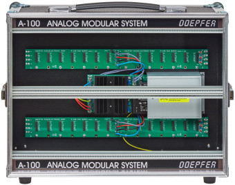
The two bus boards and the standard power supply are mounted at the rear panel. Consequently the rear panel cannot be removed.
The upper picture shows an example that includes two Theremin modules A-178 and the Analog/Trigger Sequencer A-155 (among others).
The lower picture shows an empty A-100 suitcase version 2 with built-in power supply A-100PSU2.
The A-100 suitcases can be used to built in the A-100 Basic System 1 and 2 . Please specify in your order if you want to have one of these systems built into a suitcase.
Even the A-100 mini system can be built into the A-100P6. In this case the lower half of the suitcase has to be filled with blind panels or modules that are not included in the mini system.
Of course the empty A-100P6 frame (just with power supply and bus boards) is available for customer specific arrangement of modules.
Measures:
outside: approx. 460 x 330 x 175 mm, without cover and rubber feet
outside: approx. 460 x 340 x 220 mm, with cover and rubber feet
inside: 2 x 84 HP x 3 U, usable depth for A-100 modules: approx. 70 mm in the power supply area (bottom right), resp. approx. 100 mm in the remaining area (measured from inner side of the front panel until end of the pc board of the module)
Quantity of bus boards: 2
Weight (without modules): about 7 kg
Maximum Output Current:
with built-in A-100PSU2 (until about end of 2015): +12V/1200mA, -12V/1200mA
with built-in A-100PSU3 (since about early 2016): +12V/2000 mA, -12V/1200mA, +5V/4000mA
In the area near the power supply (bottom right) no modules should be assembled that are sensitive against transformer hum. We recommend to assemble only control voltage modules in this area (e.g. LFO, ADSR, trigger delay, clock divider/sequencer, sequencer, slew limiter, MIDI interfaces and so on) but no audio modules (VCO, VCF, VCA, VCP, frequency shifter, ring modulator, spring reverb and so on). Even modules width increased depth (e.g. A-113 or A-126) cannot be assembled in the power supply area. They have to be placed in a position outside the power supply area. But this applies only for a few modules. Normally it is no problem to arrange all modules by mounting modules with smaller depth in the power supply area.
